:: Theoretical basics
| The functioning mechanism |
In the following section we shall describe the steps taken in the algorithm that ARToolkit uses for image processing.
- The first step consists of capturing the image.
- After which applying a filter is necessary for localizing the marker. This filter is also known as the binarization step, in which the initial data is transformed, by color differencing, into a black and white picture that can now be easily represented with binary code, and thus stored for further processing.
- The edge detection takes place: the contour lines’ positions are estimated, which are afterwards parameterized.
- The marker’s corners are calculated at a sub-pixel level.
- The obtained image is normalized.
- The known symbols are loaded into the application and associated with the real situation.
- The marker’s homography is calculated (Homography is a mathematical concept that is defined as the relation between two geometrical figures, so that any point in one of the figures corresponds to one and only one point in the other, and vice-versa).
- Relative transformations between the camera and the marker are calculated, and optimizations are applied. This results in parameters which are to be used by the application.
This algorithm is repeated for every frame of the video capture.
Latest attempts to overcome the limits of the current solution imply the use of neural networks to solve the problem of marker detection and interpretation .
The main strength of neural networks is corelating information with pre-made templates and even adapting the templates to environment changes.
The learning and pattern recognition abilities are possible because of the adaptive sensibility of the neurons that are the basic elements of these networks, sensibility also known as adaptive threshold.
Using this technology may revolutionize the adaptability of the system, making it resilient to luminosity changes that are so frequently encountered in real scenarios and giving it the ability to recognize also real objects, apart from markers.
|
| Implementation versions |
When implementing the IIUBAR system, there were three different solutions taken into consideration.
- Mobile system with one marker per objective,
- Fixed system with one marker per objective,
- Fixed system with one marker per environment.
In the following paragraphs we consider useful the observations made based on the analysis of the implementation possibilities of the system. Thus we will specify details about each solution and will argument the solution chosen for final implementation.
|
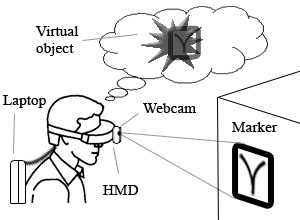
Mobile system with one marker per objective
The system configuration in this case assumes that a marker is created for each and every objective from the real world, and that a 3D model is associated with each marker. The hardware solution relies on linking and synchronizing a webcam and a HMD (head mounted display) with a laptop that would be bared by the user. (image on the left).
Advantages: Because of the portability of the HMD, this configuration proves a high level of mobility, without binding the user to one point.
Disadvantages: As the HMD, and thus the camera, moves simultaneous with the user, the stability of the captured images is below average. Because these images are the only modality for the user to perceive the environment, this version is not feasible.
|
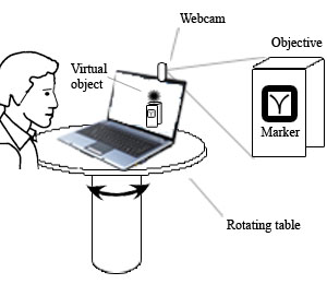
Fixed system with one marker per objective
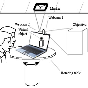
The configuration in this case is simplified in the sense that a touring table is used in place of the HMD (image on the right).
Advantages: The lack of the trepidations that we found in the previous version makes this configuration superior in the sense of image clarity.
Disadvantages: Having a fixed point from which the detection is made, the markers found far away from the system would not be clearly detected nor visualised. Thus the system’s capacity to provide the solicited information decreases dramatically.
|
|
|
Fixed system with one marker per environment
To combine the advantages of the two previous solutions, for the final implementation we opted for the fixed solution with a single marker per environment.
This version assumes two modifications: one at the hardware level and the other at the software level. The hardware change is represented by an additional camera, so that we are able to split assign each the roles of harvesting real images and the other of detecting the rotation angle relative to the marker.
The present configuration benefits from a 360o vision field, by using the rotating stand that was introduced in the previous version, and from an significantly superior image clarity and resolution, made possible by combining the images of the two webcams.
Advantages: Because the way in which it was design, this system has a high sensibility to the user’s orientation; it is adaptable to the environment in which it is placed (changing the 3D model one can satisfy the requirements of any new environment); it benefits from a very high image stability.
Disadvantages: The lack of mobility because of the fixed stand on which the system is placed, and the necessity of installing it indoors.
|
|
| Developing the 3D model |
The language used for building the virtual 3D model is VRML (Virtual Reality Modelling Language). There are several reasons for which we opted for this language. Firstly, the VRML standard is supported by the ARToolkit platform and permits the rapid description of complex geometries, unlike OpenGL. Secondly, using this file format, the IIUBAR system is easily adaptable to different configurations of the real environments.
An exceptionally important factor in creating the model is relating it to the space in which the system will be placed. For an optimum functionality, prior measurements are required to determine the distances between the positions where virtual objects are to be placed. The lower the measurement error is, the higher the precision with which the virtual and real worlds overlap (Fig. 2).
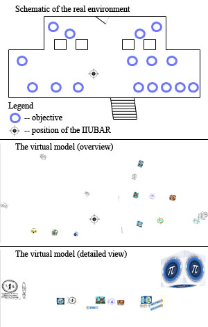
Fig. 2 The virtual 3D model
|
|
|